Test Methods
Electrical Properties of Plastics
Certain thermoplastics are good electrical insulators and offer freedom of design in electrical applications. Electrical properties may also be changed by environmental conditions such as moisture and / or temperature.
A basic concept to remember is that electrons must be exchanged between molecules for electric current to flow through a material. Plastic molecules hold on to their electrons and do not permit the electrons to flow easily — therefore we can refer to certain plastics as insulators or having insulating properties. The molecules in plastics are also "polar" which means that they will tend to act like little magnets and align themselves in the presence of a voltage or field, the same as the needle in a compass trying to point North. The electrical properties of thermoplastics can be described by the following:
- Volume resistivity
- Surface resistivity
- Dielectric constant
- Dielectric strength
- Dissipation factor
- Arc resistance
- Mechanical properties of plastics
In this we will cover the technical terms and concepts used to describe the properties or performance of thermoplastic materials. These STANDARDIZED terms are used by suppliers and users to communicate how a material behaves under specific conditions. This allows comparisons of different materials.
DESIGN
A designer or engineer will often use design equations that work with metals while a part is being designed. Metals behave like a spring; that is, the force generated by the spring is proportional to its length. A plot (FigureE 2) of the force as a function of length is a "straight line."
When a material actually works this way it is called "linear" behaviour. This allows the performance of metals and other materials that work like a spring to be quite accurately calculated. A problem occurs when the designer tries to apply these same equations directly to plastics. Plastics DO NOT BEHAVE LIKE A SPRING (not a straight line), that is they are "non-linear". Temperature changes the behaviour even more. How much load or force will the part be required to carry? How will the part be loaded? What are the direction and size of the forces in the part? These are but a few of the questions that a designer tries to answer before a material is selected.
- Stress
- Stiffness
- Strain
- Yield point
- Tensile strength
- Elongation
- Compressive strength
- Shear strength
- Flexural strength
- Torsional strength
- Creep
- Fatigue strength
- Impact strength
- Notch sensitivity
- Thermal properties of plastics
With a change in temperature, plastics materials tend to change size considerably more than other materials, such as steel, ceramics, and even aluminium. A designer must consider these differences in the sizes. In fact, the shipping environment may expose the part to a much greater temperature variation than the part will ever see in use. The measure of how much a part changes size as the temperature changes is called the THERMAL CO-EFFICIENT OF EXPANSION.
- Coefficient of expansion
- Deflection temperature under load
- Electrical properties of plastics
-
VOLUME RESISTIVITYOpen or Close
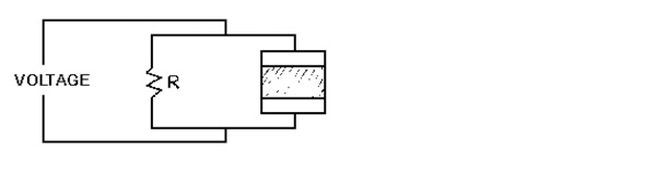
The Volume Resistivity is defined as the ratio between the voltage (Direct Current or DC), which is like the voltage supplied by a battery and that portion of current which flows through a specific volume of the specimen. Units are generally ohm per cubic centimetre.
Visualize putting DC electrodes on opposite faces of a one centimetre (.394 inch) cube of a plastic material. When a voltage is applied, some current will flow in time as the molecules align themselves.
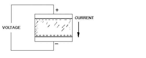
Ohm's Law tells us that a voltage (volts) divided by the current (amps) is equal to a resistance (ohms) or V/I = R. When the voltage applied to the cube is divided by the current, the resistance for 1 cm of the plastic is determined or ohm per cm.
Generally plastics are naturally good insulators and have very high resistance. The Volume Resistivity can change with temperature and the presence of moisture or humidity.
-
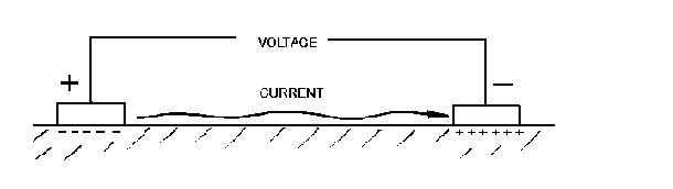
SURFACE RESISTIVITYOpen or Close
The Surface Resistivity is the ratio between the direct voltage (DC) and current along the surface per unit width. Units are generally ohms. Again referring to Ohm's Law, The Surface Resistivity is a measure of how much the surface of the material resists the flow of current.
-
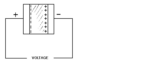
DIELECTRIC CONSTANTOpen or Close
The Dielectric Constant is the ratio of the capacitance (AC voltage) of electrodes with the insulating material between them to the capacitance of the same electrodes with a vacuum or dry air in between. The dielectric constant is a measure of how good a material works to separate the plates in a capacitor. Remember that the molecules are like little magnets and are trying to realign themselves every time the voltage (current) changes direction. Some materials do it better than others.
The dielectric constant for a vacuum has a value of 1. Dry air is very nearly 1. All other materials have "dielectric constants" that are greater than 1. The "dielectric constant" for a plastic material can vary with the presence of moisture, temperature, and the frequency of the alternating current (and voltage) across the plates.
The units for frequency are usually "HERTZ (Hz)" which means cycles per second. 3 kilohertz is the same as 3,000 hz and 3 megahertz is the same as 3,000,000 hz.<br>
-
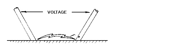
DIELECTRIC STRENGTHOpen or Close
Dielectric Strength is the voltage difference (DC) between two electrodes at which electrical breakdown occurs and is measured as volts per mil of thickness. This is an indication of how effective an "insulator" the material is.
The test is similar to that used for "Volume Resistivity" except the voltage is increased until there is an arc across the plates. This means that the voltage was strong enough to break down the material and allow a large current to flow through it. Again this property can be affected by the presence of moisture and temperature. Frequency may also affect this property when the material is subjected to an Alternating Current.
-
DISSIPATION FACTOROpen or Close
The Dissipation Factor (AC) is the tangent of the loss angle of the insulating<br> material. It can also be described as the ratio of the true in-phase power to the reactive power, measured with voltage and current 90 degrees out of phase.
This is an indication of the energy lost within the material trying to realign the molecules every time the current (voltage) changes direction in alternating current. The property varies with moisture, temperature, and frequency.
-
ARC RESISTANCEOpen or Close
The Arc Resistance is the elapsed time in which the surface of the material will resist the formation of a continuous conductive path when subjected to a high-voltage (DC), low-current arc under rigidly controlled conditions.